What we are building:
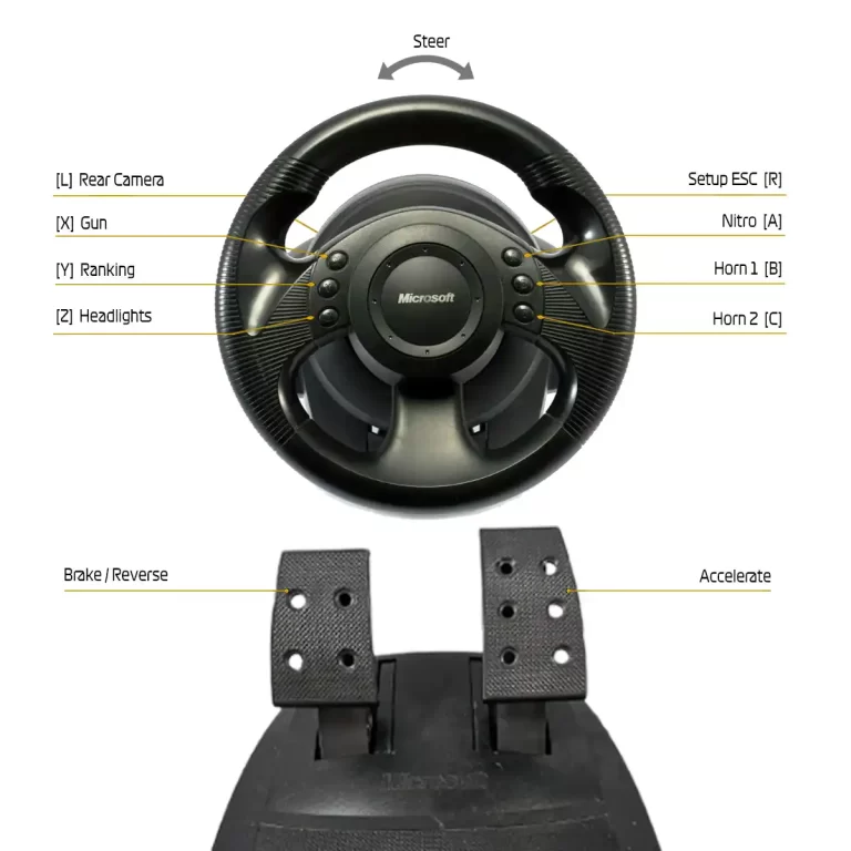
In this tutorial we will learn how to make a custom RC Transmitter by modifing a Microsoft Sidewinder Steering Wheel with the board ESP32-C6 Super Mini and ADXL345 Accelerometer.
It’s incredibly easy.
Buy the necessary parts
- ESP32 C6 Super Mini…….…….… Amazon / Banggood / Shopee
- ADXL345 Accelerometer…….… Amazon / Banggood / Shopee
- Thin wires 22 Awg…….…………… Amazon / Banggood
- 5V Power Bank (optional).…….… Amazon / Banggood
- Steering wheel and pedals set with potentiometers and buttons on them.
Disclosure: These are affiliate links. I earn a little comission if you use my links to buy the parts.
Please use them to help me continue building cool projects.
Modifying the Pedals
The pedals have 2 potentiometers. One for each pedal. They will probably be wired in a different way then what we need. So open the pedal and make sure the wires are like the last image below:
Modifying the Steering Wheel
Steering Wheel (back part):
It has 1 potentiometer and a PCB
The version with Force feedback also has a motor and a different PCB on the back part of the steering wheel cover.
We’ll not use them either.
Steering Wheel (the actual wheel):
We only need to solder a few wires on the PCB inside the wheel with the buttons.
But first, let’s cut off the PCB vias to isolate the buttons on the PCB.
I used a metal file to scratch the contacts and separate the buttons to “disconnect” them from the PCB circuit and make them individual buttons.
How to connect the wires

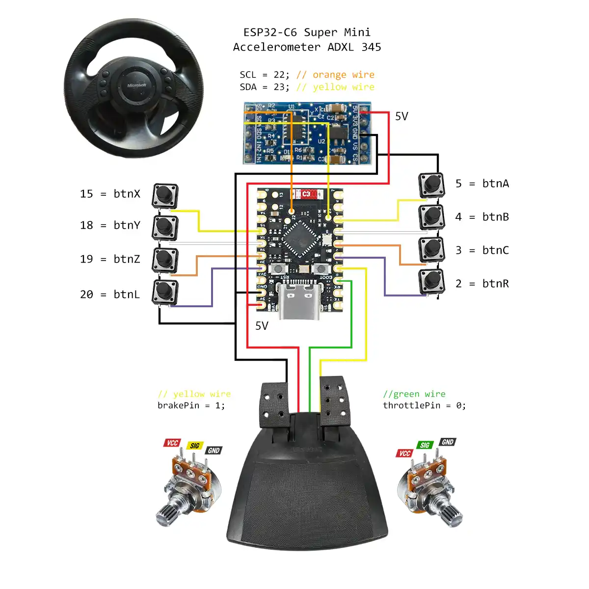
Wiring Diagram Overview:
Let’s break down the wiring based on the schematic provided.
ADXL345 Accelerometer:
- SDA (Orange Wire): Pin 22
- SCL (Yellow Wire): Pin 23
- VCC (Red Wire): 5V Pin
- GND (Black Wire): GND Pin
Steering Wheel Buttons:
Each button connects one side to a designated pin and the other side to GND.
- Button X: Pin 15
- Button Y: Pin 18
- Button Z: Pin 19
- Button L: Pin 20
- Button A: Pin 5
- Button B: Pin 4
- Button C: Pin 3
- Button R: Pin 2
Pedals:
- Throttle Pin (Green Wire): Pin 0
- Brake Pin (Yellow Wire): Pin 1
- VCC (Red Wire): 5V Pin
- GND (Black Wire): GND Pin
Power Connections:
Connect the 5V and GND pins on the microcontroller to the corresponding power rails on your breadboard if you use one.
Change the Code
You’ll need to modify the MAC ADDRESS to send the messages via ESP-NOW to the vehicle board. Learn how here.
uint8_t broadcastAddress[] = {0x54, 0x32, 0x04, 0x03, 0x2f, 0xbc};
You may need to calibrate the Accelerometer and adjust the offset values too
// int X_offset = 0, Y_offset = 0, Z_offset = 0; // Offset values
int X_offset = 57, Y_offset = 61, Z_offset = -6; // Offset values
If Steering wheel is reversed (when you turn left, the car wheels turn right) change the last two values to correct.
					mappedRawY = map(Y_out, 0, 512, 180, 0); // change this
mappedRawY = map(Y_out, 0, 512, 0, 180); // to this
Install Necessary Libraries
Open the Arduino IDE and ensure you have the necessary libraries installed for the ESP32.
Testing Your Setup
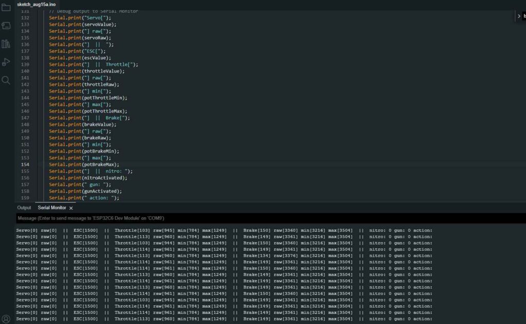
Once everything is wired and the code is uploaded, open the Serial Monitor in the Arduino IDE (Tools > Serial Monitor). You should see readings from the accelerometer, throttle, brake, and button states.

This project allows you to capture inputs from a steering wheel and pedals, providing real-time feedback on button presses and accelerometer data.

Now move on to modify the vehicle
YAY! Let’s go.
FAQ & Troubleshooting
Yes, works the same
Sure, but make sure it has potentiometers on the pedals too and connect the buttons accordinly.